
|
UberTools GDK Level Design Scripting Older Documentation Other |
Quake 3: Arena
Shader Manual with FAKK2 Additions
1 Introduction
The graphic engine for Quake 3: Arena has taken a step forward by putting much more direct control over the surface qualities of textures into the hands of designers and artists. In writing this manual, we have tried to define the concepts and tools that are used to modify textures in a way that, it is hoped, will be graspable by users who already have basic knowledge of computer graphics but are not necessarily computer programmers.
Shaders are short scripts that define the properties of surfaces and volumes as they appear or function in the game world; or compatible editing tool. By convention, the shader file is named based from the contents of the file, i.e. the texture set contained in the file. Several specific script documents are also usually created to handle special cases such as, liquids, skies, fogs, sprites, models and special effects.
1.1 Shader File Location
The shader files are located in: basedirectory/basegame/scripts.
For Quake 3 this would be something like C:\Quake3\BaseQ3\scripts
For FAKK2 this would be something like H:\HM\FAKK\scripts
The shader format consists of the following parts. A name used to reference the script. Global attributes including rendering specific commands. Tool specific commands that only affect the compiling process. Editor specific commands; and finally stage declarations, defining all the steps to create the effect.
1.2 Shader and Texture Names
A shader name often mirrors the relative path of a texture, with out
the extension. This makes it simpler for level designers and modelers
use images for creation and editing purposes.
Shaders that are only going to be referenced by the game code, or designer
placed entities are not mirrored, and often are just a single word like
“projectionShadow”, or “bloodsprite1”.
Shaders that are used on characters or other polygon models may or may
not mirror an image file. TIKI images can have multiple surfaces that
point to Targa files directly, or shader effects.
Shaders that are placed on surfaces in the level editor commonly do mirror
an image file for simplicity. Cases in which they do not include; fog
which has no displayed surface in the game; it only instructs the game
to modify a volume; and clipping volumes. The qer_editorimage command
should be used to display a representing texture.
Textures that are referenced by shaders can exist anywhere under the basedir/gamedir
path. With that in mind there are some conventions that can be followed
to keep things a bit more organized.
Shaders that will be placed on world surfaces should have a name that starts with “textures/”, as the editor is setup to only look for textures under the texture subdirectory. Textures files used in the shaders that will only be placed in the editor should all live under the texture subdirectory. Starting all shader names that will be placed on triangle models with “models/” would be prudent as well.
Design Note: qer_editorimage can also be used to set the base size of a texture. If the qer_editorimage texture is 128x128, then a stage textures are scaled to fit a 128x128 unit size.
1.3 Shader Keywords
The keywords used in shader scripts are divided into two classes. The first class of keywords are global parameters. Some parameters, keywords that start with q3map, are processed by the map compiling application (Q3MAP) and change physical attributes of the surface that uses the shader and can affect the player. To see changes in these parameters one must recompile the map. The renderer interprets the remaining global keywords and all stage specific keywords. Changes to any of these attributes will take effect as soon as the game goes to another level or vid_restarts.Keywords are not case sensitive, but pathnames have a case sensitivity issue – on windows, they aren’t case sensitive, but on Unix based systems they are. It is a good idea to make all image file names lowercase, and use only lowercase in the shaders. Also, only use forward slashes “/” for directory separators.
Design Note: Some of the shader commands may be order dependent, so it’s good practice to place all global shader commands (keywords defined in this section) at the very beginning of the shader and to place shader stages at the end.
1.4 More Advanced Shader Concepts
Ideally, a designer or artist who is manipulating textures with shader files has a basic understanding of waveforms and mixing colored light. If not, there are some concepts you need to have a grasp on to make shaders work for you.A “texture” in the game does not have to be just a simple image file. One of the most powerful abilities of a shader is building multi-texture materials that can look more realistic and dynamic in the game than simple static images.
While any shader can be placed on any shader compatible surface, keep in mind that not all commands make sense in all situations. For example, surfaceparm commands have no effect on models, as they are not process by the map compiler. Volume commands such as fogParms have no effect on patches, since patches have no volume, only a surface.
1.4.1 Surface Effects, Content Effects, and Deformation Effects
Shaders not only modify the visible aspect of brush, patch, or model geometry seen in the game, but can also have an effect on both the content and “shape” of those primitives. A surface effect does nothing to modify the shape or content of the brush. Surface effects include glows, transparencies, and RGB value changes. Content brushes affect the way the brush operates in the game world. Examples include liquids, fog, and special clipping volumes. Deformation effects change the actual shape of the affected polygons.
1.4.2 Power Has a Price
The shader script gives the designer, artist and programmer a great deal of easily accessible power over the appearance of and potential special effects that may be applied to surfaces in the game world. But, it is power that comes with a price tag attached, and the cost is measured in performance speed. Each shader stage that affects the appearance of a texture causes the Q3:A engine to make another processing pass and redraw the world. Think of it as if you were adding all the shader effected triangles to the total r_speed count for each stage in the shader script. A shader-manipulated texture that is seen through another shader manipulated texture (e.g.; a light in fog) has the effect of adding the total number of passes together for the affected triangles. A light that required two passes seen through a fog that requires one pass will be treated as having to redraw that part of the world three times.1.4.3 RGB Color
Mixing red, green and blue light in differing intensities creates the colors in computers and television monitors. This is called additive color (as opposed to the mixing of pigments in paint or colored ink in the printing process, which is subtractive color). In Quake 3: Arena and in nearly every computer art program, the intensities of the individual Red, Green, and Blue components are expressed as number values. When mixed together on a screen, number values of equal intensity in each component color create a completely neutral (gray) color. The lower the number value (towards 0), the darker the shade. The higher the value, the lighter the shade or the more saturated the color until it reaches a maximum value of 255 (in the art programs). All colors possible on the computer can be expressed as a formula of three numbers. The value for complete black being 0 0 0, and the value for pure white is 255 255 255. However, the Quake 3: Arena graphics engine requires that the color range be “normalized” into a range between 0.0 and 1.0.
1.4.4 Normalization: a Scale of 0 to 1
The mathematics in Quake 3 uses a scale of 0.0 to 1.0 instead of 0 to 255. Most computer art programs that can express RGB values as numbers use the 0 to 255 scale. To convert numbers, divide each of the art program’s values for the component colors by 255. The resulting three values are your Quake 3: Arena formula for that color’s components. The same holds true for texture coordinates. Targa texture files are measured in pixels (picture elements). Textures are measured in powers of 2, with 16 x16 pixels being the smallest (typically) texture in use. Using powers of 2 is recommended as most graphics accelerators that will run Q3:A resize images that are sent to them to a power of 2 size.
1.4.5 Color Math
In Quake 3, colors are changed by mathematical equations worked on the textures by way of the scripts or “program-lets” in the shader file. An equation that adds to a texture causes it to become lighter. Equations that multiply number values in a texture cause it to become darker. Either equation can change the hue and saturation of a color.1.4.6 Measurements
The measurements in this document are given in pixels, texels, game units or “textures”.Game unit: A game unit is how that pixel is expressed in the editor.
Typically, a game unit measure one pixel in the X, Y, and Z directions.
If not scaled or otherwise manipulated, a 128x128 pixel texture will fill
a 128x128 game unit surface.
Pixel: Is the absolute value of a single definable color coordinate in
a piece of source art.
Texel: This is how a pixel is expressed in the game world. Without manipulation,
it equals 1.0 game units.
Texture: This is the normalized (see above) dimensions of the original
texture image (or a previously modified texture at a given stage in the
shader pipeline). A full texture, regardless of its original size in pixels,
has a normalized measurement of 1.0 x 1.0.
1.4.7 Waveform Functions
Many of the shader functions use waveforms to modulate texture effects. Where appropriate, additional information is provided with wave modulated keyword functions to describe the effect of a particular waveform on that process. Currently there are five waveforms in use in Q3A shaders.
sin: Sin stands for sine wave, a regular smoothly flowing wave.
triangle: Triangle is a wave with a sharp ascent and a sharp decay. It
will make a choppy looking wave.
square: A square wave is simply on or off for the period of the frequency
with no in between state.
sawtooth: in the sawtooth wave, the ascent is like a triangle wave, but
the decay cuts off sharply like a square wave.
Inversesawtooth: This is the reverse of the sawtooth … instant ascent
to the peak value, then a triangle wave descent to the valley value. The
phase on this wave goes from 1.0 to 0.0 instead of 0.0 to 1.0. This wave
is particularly useful for additive cross fades.
1.4.8 Waveform Properties:
Base: Where the waveform begins. Amplitude is measured from this base
value.
Amplitude: This is the height of the wave created, measured from the base.
You will probably need to test and tweak this value to get it correct.
The greater the amplitude, the higher the wave peaks and the deeper the
valleys.
Phase: This is a normalized value between 0.0 and 1.0. It is the only
normalized value among the waveform parameters. Changing phase to a nonzero
value affects the point on the wave at which the wave form initially begins
to be plotted. Example: a phase of 0.25 means it begins one fourth (25%)
of the way along the curve or more simply put, it begins at the peak of
the wave. A phase of 0.5 would begin at the point the wave re-crosses
the base line. A phase of 0.75 would be at the lowest point of the valley.
If only one waveform is being used in a shader, a phase shift will probably
not be noticed and phase should have a value of zero. However, including
two or more stages of the same process in a single shader, but with the
phases shifted can be used to create interesting visual effects. Example:
using rgbGen in two stages with different colors and a 0.5 difference
in phase would cause the manipulated texture to modulate between two distinct
colors.
Frequency: This value is expressed as repetitions or cycles of the wave
per second. A value of one would cycle once per second. A value of 10
would cycle 10 times per second. A value of 0.1 would cycle once every
10 seconds.
1.5 A Basic Shader
Example 1.: How a fairly basic light-mapped texture’s shader could look:
textures/walls/basicwall
{
	deformVertexes wave sin 0 3 0 0.5
	surfaceparm nodamage
	qer_editorimage textures/wall/qer_basicwall.tga
	{
		map $lightmap
	}
	{
		map textures/wall/basicwall.tga
		blendFunc GL_DST_COLOR GL_ZERO
	}
}
1.5.1 The Basic Shader Expanded
Example 2.: Our basic shader broken down
textures/walls/basicwall
// Name of the shader, may be up to 63 characters long.


{
// First open brace, global parameters will follow.


	deformVertexes wave sin 0 3 0 0.5
// Global attribute recognized by the game only.
// This would cause to surface to ripple like a water surface.


	surfaceparm nodamage
// Surface parameter, used by the compiling tool only.
// Tells the game that this surface should not display decals.


	qer_editorimage textures/wall/qer_basicwall.tga
// This option is only recognized by the editor. Indicates
// the texture that should represent the shader in the editor.
// Overrides the shader name, see "Shader Name Mirroring".


	{
// Stage declaration

		map $lightmap
		// Texture map to be used in this stage.
		// $lightmap indicates use the lightmap data generated by
		// the tools for this specific surface
	}
// End stage declaration


	{
// Stage declaration

		map textures/wall/basicwall.tga
		// Texture map to be used in this stage.
		// This is a relative path appended to basedir/gamedir.


		blendFunc GL_DST_COLOR GL_ZERO
		// Blending function, tells the game how to overlay this
		// texture over any existing data in the framebuffer.
		// See "blendFunc".


	}
// End stage declaration


}
// End of global parameters and shader
1.6 A More Advanced Shader
Example 3.: A more complex shader, which modifies the surface, volume, and deformation.
textures/liquid/basicwater
{
	deformVertexes wave sin 0 3 0 2
	surfaceparm nolightmap
	surfaceparm trans
	surfaceparm water
	surfaceLight 1000
	surfaceColor 0.3 0.3 1.0
	tessSize 128
	qer_editorimage textures/walls/qer_basicwall.tga
	qer_trans 0.5
	{
		map textures/waters/bluewater1.tga
		blendFunc GL_SRC_ALPHA GL_ONE_MINUS_SCR_ALPHA
		tcMod scroll 0.05 -0.025

	}
	{
		map textures/waters/bluewater2.tga
		blendFunc GL_SRC_ALPHA GL_ONE_MINUS_SCR_ALPHA
		alphaGen constant 0.3
		tcMod scroll -0.03 0.01
	}
}
2 General Shader Keywords
These Keywords are global to a shader and affect all stages. The compiling tool ignores them.
2.1 cull <front|back|none>
Every surface of a polygon has two sides, a front and a back. Typically, we only see the front or “outside”. In many applications we see both. To cull means to remove. The parameter determines the type of face culling to apply. The default value is cull front if this keyword is not specified. However, for items that should be inverted then the value back should be used. To disable culling, the parameter none should be used. Only one cull instruction can be set for the shader.
2.1.1 cull front
The front or “outside” of the polygon is not drawn in the
world. This is the default value. It is used if the keyword cull appears
in the content instructions without a value or if the keyword cull does
not appear at all in the shader.
2.1.2 cull back
This removes the back or “inside” of a polygon from being
drawn in the world.
2.1.3 cull disable, cull none
Neither side of the polygon is removed. Both sides are drawn in the game.
Very useful for making panels or barriers that have no depth, such as
grates, screens, metal wire fences, etc. Also useful for liquid volumes
that the player can see from within, or for energy fields, sprites, and
weapon effects.
2.2 deformVertexes <bulge|wave|move|projectionShadow|autoSprite|autoSprite2|
text[0-7]> <…>
This function performs a general deformation on the surface’s vertexes. Vertex deformations can be applied to any surface, with some limitations (see below). When applying wave deformations to a brush surface, use of the tessSize parameter is adivsed.
2.2.1 deformVertexes autoSprite
This function can be used to make any given triangle quad automatically
behave like a sprite without having to make it a separate entity. This
means that the "sprite" on which the texture is placed will
rotate to always appear at right angles to the player's view as a parallel
sprite would. Any four-sided brush side, flat patch, or pair of triangles
in a model can display the sprite. The brush face containing a texture
with this shader keyword must be square.
2.2.2 deformVertexes autoSprite2
Is a slightly modified version of deformVertexes autoSprite that always
stays pointing up, so that fire and other images with a definite base
will never turn on their sides. However, they will look very thin when
viewed from above or near directly below). The brush face containing a
texture with this shader keyword must be square.
Design Note: This function can be used to good effect for lamp and fire objects, where instead of having a faceted approximation of a lamp globe, a glowing sprite can be used to define it.
2.2.3 deformVertexes bulge <width> <height> <speed>
???
width: ???
height: ???
speed:???
2.2.4 deformVertexes move <vector> <function> <base>
<amplitude> <phase> <frequency>
???
Vector:
Function: May be any waveform
Base, Amplitude, Phase, Frequency: See section “Waveform Functions”
2.2.5 deformVertexes projectionShadow
???
2.2.6 deformVertexes <text0|text1|text2|…|text7>
???
2.2.7 deformVertexes wave <div> <function> <base>
<amplitude> <phase> <frequency>
This makes the surface oscillate up and down in regular waves without
the appearance of movement in any particular direction. The wave’s
movement is perpendicular to the normal of the surface.
Div: This is roughly defined as the size of the waves that occur. It
is measured in game units. Smaller values create a greater density of
smaller waveforms occurring in a given area. Larger values create a lesser
density of waves, or otherwise stated, the appearance of larger waves.
To look correct this value should closely correspond to the value (in
pixels) set for tessSize (tessellation size) of the texture. A value of
100.0 is a good default value; which means your tessSize should be close
to that for things to look “wavelike”.
Function: May be any waveform.
Base: The number of game units up or down the surface normal that the
actual drawn surface is based. This can be useful for creating special
effects; like the Quad effect in Quake3; or to control cracks or gaps
in adjacent surfaces.
Amplitude, Phase, Frequency: See section “Waveform Properties”.
2.2.8 deformVertexes normal <ampliturde> <frequency>
Deforms vertexes along vertex normals, can be used to create effects without
creating cracks.
2.3 endif
Ends an if statement (see if).
2.4 entityMergable
Allows sprite surface from multiple entities to be merged into one batch. This can save rendering time for smoke puffs and blood, but can't be used for anything where the shader references the entity color or scrolls.
2.5 fogonly
This keyword needs to be a part of any fog texture. Both it, and “surfaceparm fog” need to exist in a fog shader.
2.6 fogparms <red> <green> <blue> <gradient size> <direction>
Creates a fog volume. The brush defining the volume should be orthogonal.
Red, Green, and Blue: These are normalized color values.
Gradient Size: This value controls, in game-units, the rate at which the
density or visual thickness of the fog increases. By making the height
of the fog brush shorter than the gradient size; the density of the fog
can be reduced (because it never reaches the depth at which full density
occurs). Likewise, making a fog brush taller than the gradient size means
that a greater depth of full density can be obtained, i.e. every pixel
at a distance greater than the gradient size will be at full density.
Direction: Currently the gradient in a fog brush can only have three direction
values. A value of 1 causes the gradient to be less dense on top and increase
in density towards the bottom of the brush. A value of –1 goes from
the least density at the bottom to greatest at the top. A value of 0 (zero)
creates a brush that is filled with fog set at full density.
The direction is now automatically determined by q3map. Q3map will determine which singular face is visible and then use that to determine the gradient.
2.7 if <0|1|mtex|no_mtex>
Conditional execution for shader scripts. Must be terminated with an endif (see endif).
0: This script block is never processed.
1: This script block is always processed.
Mtex: This script block is only processed if the renderer is running in
multi-texture mode.
No_mtex: This script block is only processed if the rendereri it not running
in multi-texture mode.
2.8 light <value>
Sets light flaring, what effect does the value have on the flare???2.9 nomipmaps:
This is used only for the console text. It is similar to nopicmip in that it forces a single level of texture detail onto the font used for the console.
2.10 nopicmip
This causes the texture to ignore user-set values for the r_picmip console command. The image will always be at its native resolution. Mostly used to keep images and text in the heads up display from blurring when user optimizes the game graphics.
2.11 force32bit
Forces all textures associated with this shader to be uploaded as 32 bit textures (assuming hardware supports it) regardless of what the console variable r_texturebits is set to. This helps keep textures from alpha not being totally destroyed when sampling down to 16-bit.
2.12 polygonOffset
Surfaces rendered with this keyword are rendered slightly off the polygon’s surface. This is typically used for wall markings and decals. The distance between the offset and the polygon is fixed. It is not a variable in Quake 3.
2.13 portal
Specifies that this texture is the surface for a portal or mirror. In the game map, a portal entity must be placed directly in front of the texture.
2.14 portalsky
Specifies that any surfaces with this property look into the skybox. In FAKK2 the skybox can be room of real geometry that should be separate from any other areas. An entity is placed in the area and given the script command “$entityname rendereffects +skyorigin”. The camera itself can be scripted like any other script object. Entity and surface culling is handled automatically. However, a portal sky cannot look into another portal sky, or itself.2.15 skyParms <farbox> <cloudheight> <nearbox>
With the addition of portal skies to the game, this feature will be rarely
used.
Specifies the relative height and coverage of up to eight cloud layers
(see Note below) and with nearbox, the potential to place images on the
sky that appear to be in front of the clouds. All cloud layers are mapped
to a single height value on the farbox.
Farbox: This parameter defines the way the cloud maps are stretched over
the shell of the sky. It may be half for clouds that only go to the horizon
or full for clouds that completely enclose the view (but not including
below the map).
Cloudheight: controls apparent curvature of the sky – lower numbers
mean more curvature (and thus more distortion at the horizons). Larger
height values create “flatter” skies with less horizon distortion.
Think of height as the radius of a sphere on which the clouds are mapped.
Good ranges are 64 to 256. The default value is 128.
Nearbox: This function is currently experimental. When completed, it should
allow for mountains (and other objects) to superimposed over the cloud
layers. This value should just be left as a -.
Design Note: If you are making a map where the sky is seen by looking
up most of the time, use a lower cloudheight value. Under those circumstances
the tighter curve looks more dynamic. If you are working on a map where
the sky is seen by looking out windows most of the time or has a map area
that is open to the sky on one or more sides, use a higher height to make
the clouds seem more natural. It is possible to create a sky with up to
8 cloud layers, but that also means 8 rendering passes and a potentially
large hit on fill-rate.
Example 4.: A sky shader
textures/skies/xtoxicsky_dm9
{
    qer_editorimage textures/skies/toxicsky.tga
    surfaceparm noimpact
    surfaceparm nolightmap
    q3map_globaltexture
    q3map_lightsubdivide 256
    q3map_surfacelight 400
    surfaceparm sky
    q3map_sun 1.0 1.0 0.5 150 30 60
    skyparms full 512 -
    {
        map textures/skies/inteldimclouds.tga
        tcMod scroll 0.1 0.1
        tcMod scale 3 2
        depthWrite
    }
    {
        map textures/skies/intelredclouds.tga
        blendFunc GL_ONE GL_ONE
        tcMod scroll 0.05 0.05
        tcMod scale 3 3
    }
}
2.16 sort <value>
Use this keyword to fine-tune the depth sorting of shaders as they are compared against other shaders in the game world. The basic concept is that if there is a question or a problem with shaders drawing in the wrong order against each other, this allows the designer to create a hierarchy of which shader draws in what order. The value here can be either a numerical value (not recommended usage) or one of the keywords in the following list (listed in order of ascending priority):
portal: This surface is a portal, it draws over ever other shader seen
inside the portal.
sky: Typically, the sky is the farthest surface in the game world. It
draws behind the rest of the world.
opaque: This surface is opaque, rarely needed since this is the default
with no blendfunc.
decal: This surface is a decal that is stuck onto a wall.
seeThrough: This surface can be seen through in parts, like grates/ladders.
Rarely used anymore.
banner: This surface is a banner that is very close to a wall.
additive: Used for some additive effects
nearest: This shader should always sort closest to the viewer, e.g. muzzle
flashes and blend blobs.
underwater: This shader is for something that is seen underwater.
Values may also be used but is not recommended, as the relative order
of the keywords should stay the same, the values may change.
2.17 spriteGen <parallel|parallel_oriented|parallel_upright|oriented>
When a shader is used as a sprite, this defines the way the sprite is viewed in the game.
parallel: The sprite normal is always pointing at the viewer.
parallel_oriented: The sprite always faces the viewer, but it can be rotated
about it’s normal.
parallel_upright: The sprite faces the viewer horizontally, but not vertically.
oriented: A fixed angle can be set for the sprite.
2.18 spriteScale <value>
Scales the sprite.
2.19 tessSize <value>
Controls the tessellation size, in game units, of the surface. This is only applicable to solid brushes, not patches, and is generally only used on surfaces that are deformed, or have certain alphaGen effects on them.
3 Q3MAP Specific Shader Keywords
These keywords change the physical nature of the textures and the brushes that are marked with them. Changing any of these values will require the map to be re-compiled. These are global and affect the entire shader.
3.1 q3map_backshader <shadername>
This allows a brush to use a different shader when you are inside it looking out. This allows water (or other) surfaces to have a different sort order or appearance when seen from the inside.
3.2 q3map_flare <flareshadername>
Create a flare on this surface utilizing the flareshader specified.
3.3 q3map_globaltexture
Use this shader in the global keyword commands whenever the tcMod scale function is used in one of the later render stages. Many problems with getting shader effects to work across multiple adjacent brushes are a result of the way q3map optimizes texture precision. This keyword resolves that.3.4 q3map_lightimage < texturepath/texturename>
This keyword generates lighting from the average color of the Targa image specified in q3map_lightimage. This keyword is mostly obsolete with the addition of surfaceColor.
3.5 q3map_lightsubdivide <value>
This allows the user to define how large, or small to make the subdivisions (triangles) in a textured surface, particularly aimed at light-emitting textures like skies. It defaults to 128 game units, but can be made larger (256 or 512) for sky surfaces or smaller for light surfaces at the bottoms of cracks.
3.6 q3map_sun <red> <green> <blue> <intensity> <degrees> <elevation>
This keyword in a sky shader will create the illusion of light cast into a map by a single, infinitely distance light source like the sun, moon, hellish fire, etc.
Red, Green, and Blue: Color is described by three normalized RGB values.
Color will be normalized to a 0.0 to 1.0 range, so a range of 0 to 255
could be used.
Intensity: Is the brightness of the generated light. A value of 100 is
a fairly bright sun. The maximum practical value is 255 as that is the
point the lightmap becomes full bright. The intensity of the light falls
off with angle but not distance.
Degrees: Is the angle relative to the direction on the map file. A setting
of 0 degrees equals east. 90 being north, 180 west, and 270 south.
Elevation: Is the distance, measured in degrees from the horizon (Z value
of zero in the editor). An elevation of 0 being more like sunrise/sunset,
An elevation of 90 being more towards noon.
Design Note: Sky shaders should probably still have a q3map_surfacelight
value. The “sun” gives a strong directional light, but doesn’t
necessarily give the fill light needed to soften and illuminate shadows.
Skies with clouds should probably have a weaker q3map_sun value and a
higher q3map_surfacelight value. Heavy clouds diffuse light and weaken
shadows. The opposite is true of a cloudless or nearly cloudless sky.
In such cases, the “sun” or “moon” will cast stronger,
shadows that have a greater degree of contrast.
3.7 q3map_surfaceLight <light value>
The shader emits light. The relative surface area of the texture in the world affects the actual amount of light that appears to be radiated. To give off what appears to be the same amount of light, a smaller texture must be significantly brighter than a larger texture.Example 5.: Taking light color from another source texture.
textures/eerie/ironcrosslt2_10000
{
    q3map_lightimage textures/gothic_light/ironcrosslt2.blend.tga
    // image to be used as the source for the light


    qer_editorimage textures/gothic_light/ironcrosslt2.tga
    // image to be used by the editor


    q3map_surfacelight 10000
    // emitted light value


    light 1
    // light can have a flare


    {
        map $lightmap
        // source texture is affected by the lightmap


    }
    {
        map textures/gothic_light/ironcrosslt2.tga
        // base light texture


        blendFunc GL_DST_COLOR GL_ZERO
        // base texture is multiplied into the lightmap (darkening)


    }
    {
        map textures/gothic_light/ironcrosslt2.blend.tga
        // blend map to highlight the bright areas of the light


        blendFunc GL_ONE GL_ONE
        // texture is added on to brighten


    }
}
3.8 subdivisions <value>
This controls the subdivision rate for any patch this shader is placed on. Lower values creates finer curves, higher creates coarser curves. The default for Q3:A is 4.0.
3.9 surfaceAngle <value>
No longer used.
3.10 surfaceColor <red> <green> <blue>
Specifies the color of light emitted from the surface. Uses normalized color values.
3.11 surfaceDensity <value>
Sets the density of the lightmap stage on a surface. Value indicates the number of world texels covered per 1 lightmap texel.3.12 surfaceLight <value>
See q3map_surfacelight.
3.13 surfaceparm <parm>
The keyword needs to proceed all surface or content keywords. Despite the name, volume attributes can be modified through this command. In a perfect world, all sides of a brush should have the same content settings even if surface attributes vary.
3.13.1 alphashadow (surface)
Causes the alpha channel in the given shader to filter light in an on-off
manner by a per-pixel basis.
3.13.2 areaportal (content)
A brush marked with this keyword functions as an area portal, a break
in the Q3MAP tree. It is typically placed on a brush inside a door entity
(but is not a part of that entity). The intent is to block the game from
processing surface triangles located behind it when the door is closed.
The brush must touch all the structural brushes surrounding the areaportal.
Design Note: Areas that are connected by more than one structural pathway are not very condusive to the use of areaportals. I.e. 2 rooms connected by 2 hallways. The areas will not be separated because successful separation requires that 1 areaportal completely block any 2 given areas.
3.13.3 cameraclip (content)
Prevents the 3rd person camera from moving into a defined volume.
3.13.4 detail (content)
Does not filter the brush into the structural BSP, which in turn reduces
the number of portals and shorten VIS processing time.
Design Note: Details (detail brushes) are to be used for the smaller volume that perform little to no VIS blocking, or would cause excessive splitting of the BSP. While detailing can massively reduce the time a full VIS compile takes, they can be overused (there must be some division of the world for effective visibility calculations to be performed). Be aware that detail volumes don’t block leaks, and don’t CSG against other polygons.
3.13.5 fog (content)
Fog defines the brush as being a “fog” volume. It is normally
combined with the general shader keyword fogonly. Polygons that exist
both inside and outside the volume will get split. In addition the game
automatically tessellates polys inside fog volumes to create the fogging
effect.
3.13.6 ladder (surface)
A player can climb this surface.
3.13.7 lava (content)
Assigns to the shader the game properties set for lava. The player can
move around like its water, but damages occupants at a fast rate.
3.13.8 monsterclip (content)
Prevents AI controlled actors from passing through the defined space.
3.13.9 nodamage (surface)
The player takes no damage if from falling on a surface with this attribute.
3.13.10 nodraw (surface)
A texture marked with nodraw will not visually appear in the game world.
Most often used for triggers, clip brushes, origin brushes, edges of windows
or other translucent textures, etc.
3.13.11 nodrop (content)
Prevents items dropped by players (monsters too?) from staying around.
Design Note: The intended use is for pits-of-death. By having a kill trigger inside a nodrop volume, killed players won't drop their weapons. The intent is to prevent unnecessary polygon pileups on the floors of pits.
3.13.12 noimpact (surface)
World entities will not impact on this texture. No explosions occur when
projectiles strike this surface and no marks will be left on it. Sky textures
are usually marked with this texture so those projectiles will not hit
the sky and leave marks.
3.13.13 nolightmap (surface)
This surface does not get a lightmap generated for it. It is not affected
by the ambient lighting of the world, nor dynamic lights.
3.13.14 nomarks (surface)
Projectiles will explode upon contact with this surface, but will not
leave marks. Blood will also not mark this surface. This is useful to
keep lights from being temporarily obscured by battle damage.
3.13.15 nosteps (surface)
The player makes no sound when walking on this surface.
3.13.16 nonsolid (surface)
This attribute indicates a brush, which does not block the movement of
entities in the game world. It applied to triggers, hint brushes, and
similar brushes.
3.13.17 origin (content)
Used exclusively for the “origin” texture, which defines the
rotation origin of an entity, or the point that matches up with destination
entities like waypoints. The brush must be orthogonal (rectangular or
square), and the origin point is the centroid of the volume.
3.13.18 playerclip (content)
Blocks player movement through the defined volume. Other game world entities
can pass through this volume.
Design Note: Generally used as an invisible barrier to ensure that the player will not access certain areas, smooth out rough and difficult to negotiate geometry, or to simplify collision on complex moving entities.
3.13.19 ricochet (surface)
This attribute caues certain projectiles to bounce off of it.
3.13.20 sky (surface)
The surface is a portal into the skybox.
3.13.21 slick (surface)
This attribute gives a surface significantly reduced friction.
Design Note: Good for slides, drop tubes, and launch tubes.
3.13.22 slime (content)
Assigns to the texture the game properties set for lava. The player can
move around like it’s water, but damages the occupant at a medium-slow
rate.
3.13.23 structural (content)
This surface attribute causes a brush to be seen by the compelling utility
as a possible break point in a BSP tree. It is used as a part of the shader
for the “hint” texture. Generally speaking, any texture not
marked as detail is by default, structural.
3.13.24 trans (content)
Polygon fragments inside a volume with this attribute are not discarded.
Furthermore, this surface will never block VIS.
Design Note: This should be placed on translucent surfaces and nonsolid surfaces, although a trans surface does not have to be nonsolid.
3.13.25 water (content)
Assigns to the texture the game properties for water.
3.14 Surface Types
The following are surface parameters that affect sounds and visuals of footsteps, impacts, and other surface interactions. Available surface types are:
- Dirt
- Glass
- Metal
- Stone
- Wood
4 Editor Instructions
These instructions only affect the texture when it is seen in the Radiant editor. They should be grouped with the surface parameters but ahead of them in sequence.
4.1 qer_editorimage <texturepath/texturename>
This keyword creates a shader name in memory, but in the editor, it displays
the Targa art image specified by <texturepath/texturename>.
The editor maps a texture using the size attributes of the Targa file
used for the editor image. When that editor image represents a shader,
any texture used in any of the shader stages will be scaled up or down
to the dimensions of the editor image. If a 128x128-pixel image is used
to represent the shader in the editor, then a 256x256 image used in a
later stage will be shrunk to fit. A 64x64-pixel image would be stretched
to fit Use tcMod scale to change the size of the stretched texture. Remember
that tcMod scale 0.5 0.5 will double your image, while tcMod scale 2.0 2.0 will halve it.
The eerie shader script contains a number of examples. It can be very useful for making different light styles (mostly to change the light brightness) without having to create a new piece of art for each new shader.
4.2 qer_nocarve
A brush marked with this instruction will not be affected by CSG subtract functions. It is especially useful for water and fog textures.
4.3 qer_trans <value>
This parameter defines the percentage of transparency that a brush will have when seen in the editor. It can have a positive value between 0 and 1. The higher the value, the less transparent the texture. Example: qer_trans 0.2 means the brush is 20% opaque and nearly invisible.
Example 6.: Using editor specific commands
textures/liquids/lavahell2
//path and name of new texture
{
qer_editorimage textures/eerie/lavahell.tga
// based on this


qer_nocarve
// cannot be cut by CSG subtract


qer_trans 0.3
// texture shows up as 70% translucent in the editor


surfaceparm noimpact
// projectiles do not hit it


surfaceparm lava
// has the game properties of lava


surfaceparm nolightmap
// environment lighting does not affect


q3map_surfacelight 3000
// light is emitted


tessSize 256
// relatively large triangles


cull disable
// no sides are removed


deformVertexes wave 100 sin 5 5 .5 0.02
// surface is deformed


fogparms 0.8519142 0.309723 0.0 128 128
// contents is a fog volume also


{
		map textures/eerie/lavahell.tga
	// base texture artwork


		tcMod turb 0.25 0.2 1.0 0.02
	// texture is subjected to turblence


		tcMod scroll 0.01 0.01
	// the turblence is scrolled
}
}
5 Stage Specific Keywords
Stage specifications only affect rendering. Changing any keywords or values within a stage will usually necessitate a vid_restart or a map reload.Design Note: Be aware that alpha channels can be utilized in 2
ways. First the command alphaFunc can render a stage texture into the
frame buffer using source alpha and comparing it to the alpha function
specified (a simple do or don’t render this pixel). Second a blendFunc
that includes GL_SRC_ALPHA or GL_ONE_MINUS_SRC_ALPHA can be used to achieve
partial translucency; windows, fades, etc.
5.1 alphaFunc <GT0|LT128|GE128>
Determines the alpha test function used when rendering this map. By default alpha testing is disabled.GT0: (greater than 0) Only portions of the texture with alpha values greater
than zero will be written into the framebuffer.
LT128: (less than 128) Only portions with alpha less than 128 will be
written.
GE128: (greater than or equal to 128) Only portions greater than, or equal
to 128 will be written.
In plain language, this means that you must add an alpha channel to the Targa image. Photoshop can do this. Paintshop Pro has the ability to make an alpha channel but appears to lack the power to do anything with it. In Photoshop you want to set the type to “mask”. Black has a value of 255. White has a value of 0. The darkness of a pixel’s alpha value determines the transparency of the corresponding RGB value in the game world. Darker means more transparent.
Care must be taken when reworking textures with alpha channels. Textures without alpha channels are saved as 24 bit images while textures with alpha channels are saved as 32 bit. If you save them out as 24 bit, the alpha channel is erased. Note Adobe Photoshop will prompt you to save as 32, 24 or 16 bit, so choose wisely. To create a texture that has “open” areas, make those areas black in the alpha channel and make white the areas that are to be opaque. Using gray shades will create varying degrees of opacity/transparency.
Example 7.: An opaque texture with see-through holes knocked in it.
textures/base_floor/pjgrate1
{
	surfaceparm	metalsteps
	cull none
	{
		map textures/base_floor/pjgrate1.tga
		blendFunc GL_SRC_ALPHA GL_ONE_MINUS_SRC_ALPHA
		alphaFunc GT0
		depthWrite
		rgbGen identity
	}
	{
		map $lightmap
		rgbGen identity
		blendFunc GL_DST_COLOR GL_ZERO
		depthFunc equal
	}
}
The alpha channel can also be used to merge a texture (including one that contains black) into another image so that the merged art appears to be and opaque decal on a solid surface (unaffected by the surface it appears to sit on), without actually using an alpha function. The following is a very simple example:
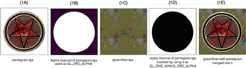
Figure 1
Start with a Targa file image. In this case, a pentagram on a plain white field (figure 1A); the color of the field surrounding the image to be merged is not relevant to this process (although having a hard-edged break between the image to be isolated and the field makes the mask making process easier). Make an alpha channel. The area of the image to be merged with another image is masked off in white. The area to be masked out (not used) is pure black (figure 1B). The image to be merged into the green floor (figure 1C).
Add a qer_editorimage pointing to greenfloor.tga. This is placed in the frame buffer as the map image for the texture. By using GL_SRC_ALPHA as the source part of the blend equation, the shader adds in only the non-black parts of the pentagram. Using GL_MINUS_ONE_SRC_ALPHA, the shader inverts the pentagram’s alpha channel and adds in only the non-black parts of the green floor.
Example 8.: The shader that builds the floor texture with a rotating pentagram overlaid.
textures/eerie/pentagramfloor_rotating
{
	qer_editorimage textures/eerie/greenfloor.tga
	{
		map $lightmap
		// lightmap is placed in the framebuffer
	}
	{
		map textures/eerie/greenfloor.tga
		blendFunc GL_DST_COLOR GL_ZERO
		// the base floor is multiplied into it (darkened)
	}
	{
		map textures/eerie/pentagram.tga
		blendFunc GL_SRC_ALPHA GL_ONE_MINUS_SRC_ALPHA
		clampTexCoords
		rgbGen wave sin 0.750000 0.250000 0.000000 0.500000
		tcMod rotate -60
		// the pentagram is overlaid
	}
}
In a like manner, the alpha channel can be used to blend the textures more evenly. A simple experiment involves using a linear gradient in the alpha channel (white to black) and merging two textures so they appear to cross fade into each other.
A more complicated experiment would be to take the pentagram in the first example and give it an aliased edge so that the pentagram appeared to fade or blend into the floor.
5.2 alphaGen <constant|dot|entity|identity|lightingSpecular|
oneMinusDot| oneMinusEntity|oneMinusVertex|portal|vertex|
wave> <…>
5.2.1 alphaGen constant <value>
Used to specify a constant alpha value without having an alpha channel
in the actual texture. This can save texture memory (image saved as 24
bit instead of 32 bit), look better on 16 bit color cards (texture can
be uploaded as 5-6-5 or similar instead of 4-4-4-4), and make it easier
to test transparency values.
5.2.2 alphaGen dot [min] [max]
Alpha value is generated from the dot product of the surface normal and
the view angle. Ranges from 0 for parallel view to 1 for perpendicular
view. Great for simulating the varying translucency of water or reflective
surfaces based on view angle.
5.2.3 alphaGen entity
Alpha is taken from the entity’s modulate field.
5.2.4 alphaGen identity
Alpha is set to identity (1.0).
5.2.5 alphaGen lightingSpecular <x y z>
Creates specular highlights in the alpha channel, typically used in conjunction
with $whiteimage.
5.2.6 alphaGen oneMinusDot
The inverse of alphaGen dot.
5.2.7 alphaGen oneMinusEntity
The inverse of alphaGen entity.
5.2.8 alphaGen oneMinusVertex
The inverse of alphaGen vertex.
5.2.9 alphaGen skyalpha
Get the alpha from the global parameter which is manipulated from script
5.2.10 alphaGen oneMinusSkyAlpha
Get the alpha from one minus the global parameter which is manipulated
from script
5.2.11 alphaGen portal [range]
When a range is specified, alpha values are generated based on the distance
from the viewer to the portal surface. To be used during the last rendering
stage.
5.2.12 alphaGen vertex
???
5.2.13 alphaGen wave <function> <base> <amplitude>
<phase> <frequency>
Modifies the alpha value using a waveform. Note that a wave could oscillate
from -1.0 to 1.0, but alpha must be clamped from 0.0 to 1.0. To create
a wave that evaluates from 0.0 to 1.0, you would need to use a base value
of 0.5 and amplitude of 0.5.
Function: May be any waveform.
Base, Amplitude, Phase, Frequency: See section “Waveform Functions”
5.3 animMap <frequency> <texture1> … <texture8>
The surfaces in the game can be animated by displaying a sequence of 1 to 8 frames (separate texture maps). These animations are affected by other keywords in the same and later shader stages.
Frequency: The number of times that the animation cycle will repeat within
a one-second-time period. The larger the value, the more repeats within
a second. Animations that should last for more than a second need to be
expressed in fractional values.
Texture1-8: The texturepath/texturename for each animation frame must
be explicitly listed. Up to eight frames (eight separate image files)
can be used to make an animated sequence. Each frame is displayed for
an equal subdivision of the frequency value.
Example 9.: A simple 2 frame animation
textures/animation/testanim
{
{
animMap 2 textures/fire/fire01.tga textures/fire/fire02.tga textures
/fire/fire03.tga textures/fire/fire04.tga
}
}
This would be a 4 frame animated sequence with each frame being called in sequence over a cycle of 2 seconds. I.e. each frame would display for 0.5 seconds. The cycle repeats after the last frame is shown.
To vary the time an image is displayed from image to image, repeat the frame in the sequence.
5.4 BlendFunc <”add”> <”filter”> <”blend”> <srcBlend> <dstBlend>
Getting a handle on this concept is absolutely necessary to understanding how to best take advantage of the shader language.
add – srcBlend = GL_ONE, dstBlend = GL_ONE
filter – srcBlend = GL_DST_COLOR, dstBlend = GL_ZERO
blend – srcBlend = GL_SRC_ALPHA, dstBlend = GL_ONE_MINUS_SRC_ALPHA
The blend function is the equation at the core of processing shader graphics. The formula reads as follows:
Source: Is the RGB color data in the current texture (remember, it’s
all numbers).
SrcBlend: The blend mode to be applied to the source image
Destination: Is the color and alpha data currently existing in the framebuffer.
DstBlend: The blend mode to be applied to the framebuffer.
Rather than think of the entire texture as a whole, it may be easier to think of the number values that correspond to a single pixel, because that is essentially what the computer is processing … one pixel of the bit map at a time.
The process for calculating the final look of a texture in the game world begins with the pre-calculated lightmap for the area where the texture will be located. This data is in the frame buffer, that is to say, it is the initial data in the Destination. In an non-manipulated texture (i.e. one without a special shader script), color information from the texture is combined with the lightmap. In a shader-modified texture, the $lightmap stage must be present for the lightmap to be included in the calculation of the final texture appearance.
Each pass or “stage” of blending is combined (in a cumulative manner) with the color data passed onto it by the previous stage. How that data combines together depends on the values chosen for the Source Blends and Destination Blends at each stage. Remember its numbers that are being mathematically combined together that are ultimately interpreted as colors.
A general rule is that any srcBlend other than GL_ONE, or GL_SRC_ALPHA where the alpha channel is entirely white, will cause the Source to become darker.
5.4.1 Source Blend <srcBlend>
The following values are valid for the Source Blend part of the equation.- GL_ONE
This is the value 1. When multiplied by the Source, the value stays the same the value of the color information does not change. - GL_ZERO
This is the value 0. When multiplied by the Source, all RGB data in the Source becomes zero, or black. - GL_DST_COLOR
This is the value of color data currently in the Destination (framebuffer). The value of that information depends on the information supplied by previous stages. - GL_ONE_MINUS_DST_COLOR
This is the same as GL_DST_COLOR except that the value for each component color is inverted by subtracting it from one
(i.e. red = 1.0 – dest. red, green = 1.0 – dest green, blue = 1.0 – dest blue). - GL_SRC_ALPHA
The image file being used for the Source data must have an alpha channel in addition to its RGB channels (for a total of four channels). The alpha channel is an 8-bit black and white only channel. An entirely white alpha channel will not darken the Source. - GL_ONE_MINUS_SRC_ALPHA
This is the same as GL_SRC_ALPHA except that the value in the alpha channel is inverted by subtracting it from one. (i.e. alpha = 1.0 – source alpha)
5.4.2 Destination Blend <dstBlend>
The following values are valid for the Destination Blend part of the equation.- GL_ONE
This is the value 1. When multiplied by the Destination, the value stays the same the value of the color information does not change. - GL_ZERO
This is the value 0. When multiplied by the Destination, all RGB data in the Destination becomes zero, or black. - GL_SRC_COLOR
This is the value of color data currently in the Source (which is the texture being manipulated here). - GL_ONE_MINUS_SRC_COLOR
This is the value of color data currently in Source, but subtracted from one (inverted). - GL_SRC_ALPHA
The image file being used for the Source data must have an alpha channel in addition to its RGB channels (four a total of four channels). The alpha channel is an 8-bit black and white only channel. An entirely white alpha channel will not darken the Source. - GL_ONE_MINUS_SRC_ALPHA
This is the same as GL_SRC_ALPHA except that the value in the alpha channel is inverted by subtracting it from one. (i.e. alpha = 1.0 – src alpha)
5.4.3 Doing the Math: The Final Result
The product of the Source side of the equation is added to the product of the Destination side of the equation. The sum is then placed into the frame buffer to become the Destination information for the next stage. Ultimately, the equation creates a modified color value that is used by other functions to define what happens in the texture when it is displayed in the game world.
5.4.4 Default Blend Function
If no blendFunc is specified, then no blending will take place. A warning is generated if any stage after the first stage does not have a blendFunc specified.
5.4.5 Technical Information/Limitations Regarding Blend Modes:
The RIVA128 graphics card supports ONLY the following blend modes:
- GL_ONE, GL_ONE
- GL_DST_COLOR, GL_ZERO
- GL_ZERO, GL_SRC_COLOR
- GL_SRC_ALPHA, GL_ONE_MINUS_SRC_ALPHA
- GL_ONE_MINUS_SRC_ALPHA, GL_SRC_ALPHA
5.4.6 blendFunc Example 1
Example 10.: A basic lightmapped surface:
{
map $lightmap
}
{
map textures/walls/sometexture.tga
blendFunc GL_DST_COLOR GL_ZERO
}
The lightmap is placed into the framebuffer, overwriting any previous data, then the texture is multiplied into the lightmap (darkening it to add shadows).
5.4.7 blendFunc example 2
Example 11.: A basic translucent surface:
{
map textures/windows/somewindow.tga
blendFunc GL_SRC_ALPHA GL_ONE_MINUS_SCR_ALPHA
// alphaGen constant 0.3
// this could be optionally used
}
Our window texture is multiplied by the value of it’s alpha channel, then added to what exists in the framebuffer times the inverted value of the somewindow.tga alpha channel.
The alphaGen constant command is optional. If it were to be used, the source image would be treated as if it’s entire alpha channel had a value of 0.3. In effect the shader would take 30% of the window, and add it to 70% of the framebuffer (whatever is behind the window). The resulting framebuffer has a color intensity between the original framebuffer and the source artwork.
5.4.8 blendFunc example 3
Effects like volumetric lighting (which brightens the scene), or many weapons effects is achieved through adding colors.
Example 12.: Translucency through addition
{
map textures/effects/volumetriclight.tga
blendFunc GL_ONE GL_ONE
}
Overall brightness can only be increased with this blending function. What existed in the framebuffer is still seen, but brightened. Textures used in additive effects are usually very dark to prevent the whole area from becoming pure white.
5.5 ClampTexCoords
ClampTexCoords is no longer used, use clampmap instead.
Dictates that this stage should clamp texture coordinates instead of wrapping them. During a stretch function, the area, which the texture must cover during a wave cycle, enlarges and decreases. Instead of repeating a texture multiple times during enlargement (or seeing only a portion of the texture during shrinking) the texture dimensions increase or contract accordingly. This is only relevant when performing texture coordinate modifications to stretch/compress texture coordinates for a specific special effect. Remember that the Q3 engine normalizes all texture coordinates (regardless of actual texture size) into a scale of 0.0 to 1.0.
5.5.1 Proper Alignment
When using this command, make sure the texture is properly aligned on the brush, as this function keeps the image from tiling. However, the editor doesn’t represent this properly and shows a tiled image. Therefore, what appears to be the correct position may be offset. This is very apparent on anything with a tcMod rotate and clampTexCoords function.
5.5.2 Avoiding Distortion
When seen at a given distance (which can vary, depending on hardware
and the size of the texture), the compression phase of a stretch function
will cause a “cross”-like visual artifact to form on the modified
texture due to the way that textures are reduced. This occurs because
the texture undergoing modification lacks sufficient “empty space”
around the displayed (non-black) part of the texture (see figure 2a).
To compensate for this, make the non-zero portion of the texture substantially
smaller (50% of maximum stretched size -- see figure 2b) than the dimensions
of the texture. Then, write a scaling function (tcMod scale) into the
appropriate shader phase, to enlarge the image to the desired proportion.
The shader for the bouncy pads shows the stretch function in use, including
the scaling of the stretched texture.
Example 13.: Using clampTexCoords to control a stretching texture.
textures/sfx/bouncepad01block18b
{
    surfaceparm nodamage
    q3map_lightimage textures/sfx/jumppadsmall.tga
    q3map_surfacelight 2000
    {
        map textures/sfx/bouncepad01block18b.tga
        rgbGen identity
    }
    {
        map $lightmap
        rgbGen identity
        blendfunc gl_dst_color gl_zero
    }
    {
        map textures/sfx/bouncepad01b_layer1.tga
        blendfunc gl_one gl_one
        rgbGen wave sin .5 .5 0 1.5
    }
    {
        clampmap textures/sfx/jumppadsmall.tga
        blendfunc gl_one gl_one
        tcMod stretch sin 1.2 .8 0 1.5
        rgbGen wave square .5 .5 .25 1.5
    }
}
5.6 depthFunc <function>
This controls the depth comparison function used while rendering. The default is lequal, less-than-or-equal-to. Where any surface that is at the same depth or closer of an existing surface is drawn. Under some circumstances you may wish to use equal, only render pixels in this stage if they are the same distance as what currently exists in the framebuffer. This is very useful for adding a lightmap to “masked” fence type textures or mirrors.
The example below is the same from alphaFunc, however, we may look at the use of depthFunc to only render the lightmap where the grate is opaque.
Example 14.: An opaque texture with see-through holes knocked in it.
textures/base_floor/pjgrate1
{
	surfaceparm	metalsteps
	cull none
	{
		map textures/base_floor/pjgrate1.tga
		blendFunc GL_SRC_ALPHA GL_ONE_MINUS_SRC_ALPHA
		alphaFunc GT0
		depthWrite
		rgbGen identity
	}
	{
		map $lightmap
		rgbGen identity
		blendFunc GL_DST_COLOR GL_ZERO
		depthFunc equal
	}
}
5.7 depthWrite
Indicates that writing to the Z-buffer during this stage should be enabled. Basically the Z-buffer handles occlusion between objects (i.e. distant objects won't get rendered in front of nearer objects).Depth writes should be enabled at all times except for windows and other transparent/translucent objects. This command should not be used on translucent objects. The only special exception is grates (e.g. any texture where the alpha channel is being used to knock holes in the texture).
By default any stage that does NOT have this flag set but that DOES have a blendFunc specified will have this flag turned off.
5.8 detail
Designates this stage as a detail texture stage, which means that if r_detailtextures is set to 0 then this stage will be ignored. This keyword, by itself, does not affect rendering at all. If you do add a detail texture, it has to conform to very specific rules. Specifically, the blendFunc:
- blendFunc GL_DST_COLOR GL_SRC_COLOR
- The average intensity of the detail texture itself must be around 127 (0.5 in Q3:A color values).
Detail is used to blend fine pixel detail back into a base texture when viewed from a close distance, and the individual pixels become very distinct. When detail is written into a set of stage instructions, it allows the stage to be disabled by the console command setting r_detailtextures 0.
A texture whose scale has been increased beyond a 1:1 ratio tends not to have very high frequency content. In other words, one texel can cover a lot of screen space. Frequency is also known as detail. Lack of detail can appear acceptable if the player never has the opportunity to see the texture at close range. But seen close up, such textures look glaringly wrong within the sharp detail the Q3:A engine can provide. A detail texture solves this problem by taking a noisy "detail" pattern (a tiling texture that appears to have a great deal of surface roughness) and applying it to the base texture at a very densely packed scale (that is, reduced from its normal size). This is done programmatically in the shader, and does not require modification of the base texture. Note that if the detail texture is the same size and scale as the base texture that you may as well just add the detail directly to the base texture. The theory is that the detail texture's scale will be so high compared to the base texture (e.g. 9 detail texels fitting into 1 base texel) that it is literally impossible to fit that detail into the base texture directly.
For this to work, the rules are as follows:
- The lightmap must be rendered first. This is because the subsequent
detail texture will be modifying the lightmap in the framebuffer directly.
- The detail texture must be rendered next since it modifies the lightmap
in the framebuffer.
- The base texture must be rendered last.
- The detail texture MUST have a mean intensity around 127-129. If it
does not then it will change the perceived brightness of the base texture
in the world.
- The detail shader stage MUST have the detail keyword or it will not
be disabled if the user uses the r_detailtextures 0 setting .
- The detail stage MUST use blendFunc GL_DST_COLOR GL_SRC_COLOR. Any
other blendFunc will cause mismatches in brightness between detail and
non-detail views.
- The detail stage should scale its textures by an amount typically
between 3 and 12 using tcMod to control density. This roughly corresponds
to coarseness. A very large number, such as 12, will give very fine
detail, however, that detail will disappear very quickly as the viewer
moves away from the wall since it will be MIP-mapped away. A very small
number, e.g. 3, gives diminishing returns since not enough detail is
apparent when the user gets very close. Non-integral scales that aren’t
quite the same for the 2 axis’ help avoid repeating patterns in
the detail.
- Since detail textures add one pass of overdraw, so there is a definite
performance hit.
- Detail textures can be shared, so often a small set of textures are created for different basic surfaces, and used multiple times.
Example 15.: Shader with a detail pass.
textures/bwhtest/foo
{
    // draw the lightmap first
    {
        map $lightmap
        rgbGen identity
    }


    // modify the lightmap in the framebuffer by
    // a highly compressed detail texture
    {
        map textures/details/detail01.tga
        blendFunc GL_DST_COLOR GL_SRC_COLOR
        // YOU MUST USE THIS blendFunc!!!


        detail
        // to allow the detail to be disabled from with in the game


        tcMod scale 9.1 9.2
        // shrunk to keep the texel density at close range high
    }


    // now slap on the base texture
    {
        map textures/castle/blocks11b.tga
        blendFunc GL_DST_COLOR GL_ZERO
    }
}
5.9 map <texturepath/texturename>, clampmap <texturepath/texturename>
Specifies the source texture map (a 24 or 32-bit TGA file) to be used in this stage. The texture may or may not contain alpha information. The special keywords $lightmap and $whiteimage may be substituted in lieu of an actual texture.
If clampmap is specified, the texture will have it’s texture coordinates
clamped instead of wrapped.
5.9.1 $lightmap
This is a reference to the lighting data that is calculated by the compiling utility for the surface that is being rendered. This needs to be combined with a rgbGen identity statement if explicitly used in a shader.
5.9.2 $whiteimage
This keyword causes the stage map to behave like a pure white image. Uses of $whiteimage include combining with alphaGen lightingSpecular to add specular highlights to a surface, or mixing with rgbGen to add a color tint.
5.10 nextbundle
Used to define the next texture in a multi-texture operation. A map command should immediately follow this command. Any stage commands may follow except for blendFunc.
Example 16.: An example of a multi-texture shader
textures/techdemo/mtexwater1
{
	cull none
	surfaceparm nolightmap
	surfaceparm trans
	surfaceparm water
	qer_editorimage textures/liquids/blue_water1.tga
	qer_trans 0.500000
	{
		map $whiteimage
		blendFunc GL_SRC_ALPHA GL_ONE_MINUS_SRC_ALPHA
		alphaGen oneMinusDot
		rgbGen constant 0.000000 0.250000 0.750000
	}
if mtex
	{
		map textures/liquids/blue_water1a.tga
		blendFunc GL_ONE GL_ONE
		tcMod scale 0.330000 0.330000
		tcMod turb 0.000000 0.200000 0.000000 0.100000
		nextbundle
		map textures/liquids/blue_water1b.tga
		tcMod scale 0.660000 0.660000
		tcMod scroll -0.050000 -0.030000
	}
endif
	{
		map textures/liquids/blue_water1a.tga
		blendFunc GL_SRC_ALPHA GL_ONE
		alphaGen lightingSpecular
		tcMod scroll 0.070000 -0.040000
	}
}
Design Note: Currently OpenGL multi-texture only allows for the textures involved in the operation to be multiplied together. This is what will happen to the 2 textures before they are placed into the frame buffer with blendFunc.
5.11 noDepthTest
Do not do Z-buffer compares when rendering the stage.
5.12 rgbGen <const|constant|entity|exactVertex|identity|identityLighting|
lightingDiffuse|oneMinusEntity|oneMinusVertex|vertex|wave> <…>
There are two color sources for any given shader, the texture Targa file and the vertex colors. Output at any given time will be equal to the TEXTURE multiplied by the VERTEX COLOR (VERTEX COLOR can only darken a texture). Most of the time VERTEX COLOR will default to white (a normalized value of 1.0), so output will be TEXTURE. This usually lands in the Source side of the shader equation.
The most common reason to use rgbGen is to pulsate something. This means that the VERTEX COLOR will oscillate between two values, and that value will be multiplied (darkening) the texture.
5.12.1 rgbGen const/constant <red> <green> <blue>
Generates a constant RGB value.
5.12.2 rgbGen entity
Colors are grabbed from the entity’s modulate field. This is used
for things like explosions.
5.12.3 RgbGen exactVertex
???
5.12.4 rgbGen identity
Colors are assumed to be all white (1.0,1.0,1.0). With the addition of
the over-bright “sunlight” emitted from the sky textures,
rgbGen identity must be included in all textures with a lightmap.
5.12.5 rgbGen identityLighting
???
5.12.6 rgbGen lightingDiffuse
Colors are computed using a standard diffuse lighting equation. It uses
the vertex normals to illuminate the object correctly.
Design Note: rgbGen lightingDiffuse is used when you want the RGB values to be computed for a dynamic TIKI model in the world using the sphere lighting. This would be used on shaders for item, characters, weapons etc.
5.12.7 rgbGen oneMinusEntity
Colors are grabbed from 1.0 minus the entity’s modulate field.
5.12.8 rgbGen oneMinusVertex
Colors are filled in directly by the client game at 1 minus the vertex
color.
5.12.9 rgbGen vertex
…
Design Note: rgbGen vertex is used when you want the RGB values to be computed for a static TIKI model in the world using precomputed static lighting from the compiling utility. This would be used on things like the plants, awnings, and other nonmoving – decorative objects placed in the world.
5.12.10 rgbGen wave <function> <base> <amplitude>
<phase> <frequency>
Colors are generated using the specified waveform. A waveform function
will cause the intensity and saturation of the base color to vary with
the wave. An affected shader with become darker and lighter, but will
not change hue. Remember that like alphaGen, the evaluated wave result
is normalized between 0.0 and 1.0.
Function: May be any waveform, or noise.
Base: Baseline value. The initial VERTEX COLOR values.
Amplitude: This is the degree of change from the baseline value. It is
a normalized value between 0.0 and 1.0.
Phase, Frequency: See section “Waveform Functions”
5.12.11 rgbGen colorwave <red> <green> <blue> <function> <base> <amplitude> <phase> <frequency>
Colors are generated by multiplying the constant color by the waveform. A waveform function will cause the intensity and saturation of the base color to vary with the wave. Remember that like alphaGen, the evaluated wave result is normalized between 0.0 and 1.0.
Function: May be any waveform, or noise.
Base: Baseline value. The initial VERTEX COLOR values.
Amplitude: This is the degree of change from the baseline value. It is
a normalized value between 0.0 and 1.0.
Phase, Frequency: See section “Waveform Functions”
5.13 tcGen,texgen <coordinate source>
Specifies how texture coordinates are generated and where they come from.
base: Base texture coordinates from the original art.
lightmap: Lightmap texture coordinates.
environment: Make this object environment-mapped.
vector <x y z> <x y z>: texture coordinates are detemined
by the dot product of the world space coordinate of the vertex and the
first vector for s and the dot product of the world space coordinate of
the vertex and the second vector for t.
5.14 tcMod <offset|rotate|scale|scroll|stretch|transform|turb|parallax|
macro> <…>
Specifies how texture coordinates are modified. As many as 4 tcMods can be used per stage. The effects of texture coordinate modifications add together. When using multiple tcMod functions during a stage, place the scroll command last in order.
An example of stacked tcMods:
The movement rate would effectively change to one half texture-per-second.
5.14.1 tcMod offset <sOffset> <tOffset>
Transforms the texture coordinates to offset the texture. This does not
require programmers.
The main use for this tcMod is for scripting of translating textures. Due to the way the Q3:A engine handles the scrolling tcMod as a function of global time, when a scroll is started, it’s starting position is not guaranteed, hence an undesired “jump” in the texture would occur before scrolling started.
5.14.2 tcMod rotate <degrees>
This keyword causes the texture coordinates to rotate. The value is expressed
in degrees rotated each second. A positive value means clockwise rotation.
A negative value means counterclockwise rotation. For example tcMod rotate
5 would rotate texture 5 degrees each second in a clockwise direction.
The texture rotates around the center point of the texture map, so if
you are rotating a texture with a single repetition, be careful to center
it on the brush (unless off-center rotation is desired).
5.14.3 tcMod scale <sScale> <tScale>
Resizes (enlarges or shrinks) the texture coordinates by multiplying them
against the given factors of sScale and tScale. The values S and T conform
to the X and Y values respectively as they are found in the original texture
image. The values for sScale and tScale are not normalized. This means
that a value greater than 1.0 will increase the size of the texture. A
positive value less than one will reduce the texture to a fraction of
its size and cause them to repeat within the same area as the original
texture.
For example: tcMod scale 0.5 2.0 would cause the texture to repeat twice
along its width, but expand to twice its height, half of the texture would
be seen in the same area as the original.
5.14.4 tcMod scroll <sSpeed> <tSpeed>
Scrolls the texture coordinates with the given speeds. The values S and
T conform to the X and Y values respectively as they are found in the
original texture image. The scroll speed is measured in textures-per-second.
A “texture unit” is the dimension of the texture being modified
and includes any previous shader modifications to the original image.
A negative S value would scroll the texture to the left. A negative T
value would scroll the texture down.
For example: tcMod scroll 0.5 -0.5 moves the texture down and right, relative to the file’s original coordinates, at the rate of a half texture each second of travel.
This should be the last tcMod in a stage. Otherwise there may be popping or snapping visual effects.
5.14.5 tcMod stretch <function> <base> <amplitude>
<phase> <frequency>
Stretches the texture coordinates with the given function. Stretching
is defined as stretching the texture coordinate away from the center of
the center of the polygon and then compressing it towards the center of
the polygon.
Function: May be any waveform.
Base: A base value of one is the original dimension of the texture when
it reaches the stretch stage. Inserting other values positive or negative
in this variable will produce unknown effects.
Amplitude: This is the measurement of distance the texture will stretch
from the base size. It is measured, like scroll, in textures. A value
of 1.0 here will double the size of the texture at it’s peak.
Phase, Freq: See section “Waveform Functions”
5.14.6 tcMod transform <m00> <m01> <m10> <m11> <t0> <t1>
Transforms each texture coordinate a la:This is for use by programmers.
5.14.7 tcMod turb <base> <amplitude> <phase> <frequency>
Applies turbulence to the texture coordinate. Turbulence is a swirling effect on the texture.Base: Has no bearing on turbulence.
Amplitude: This is essentially the int
ensity of the disturbance, or twisting and squiggling of the texture.
Phase, Frequency: See section “Waveform Functions”
5.14.8 tcMod parallax <sRate> <tRate>
Dynamically scrolls the texture coordinates based off of the current view
coordinates. Allows you to setup multiple scrolling parallax layers similar
to side scrolling engines.
5.14.9 tcMod macro <sScale> <tScale>
Creates world aligned texture coordinates to be used for macro texturing
6 Script Shader Manipulation
Certain shader parameters can be controlled through the map script. In order to do this, two things must be done; the shader must be placed on B-model surfaces in the world, and fromEntity must be substituted for any values that you would like to control. Shader commands that may be controled via the script include:
- tcMod scroll <fromEntity> <fromEntity>
- tcMod rotate <fromEntity>
- tcMod offset <fromEntity> <fromEntity>
- deformVertexes wave <div> <waveform> <wave> <fromEntity> <fromEntity> <fromEntity> <fromEntity>
- alphaGen wave <waveform> <fromEntity> <fromEntity> <fromEntity> <fromEntity>
- rgbGen wave <waveform> <fromEntity> <fromEntity> <fromEntity> <fromEntity> lt;frameFromEntity> - See example of scripted texture animation.
The fromEntity keyword may be mixed with constant values as desired.
Any shader function that uses a waveform can use the fromEntity substitutions.
You can also set the animation frame on a shader by using the command
frameFromEntity.
6.1 Script Commands
- shader offset [x] [y]
- shader rotation [degrees]
- shader translation [x] [y]
- shader frame [framenum]
- shader wavebase [base offset of wave function]
- shader waveamp [amplitude of wave function]
- shader wavephase [phase of wave function]
- shader wavefreq [frequency of wave function]
Example 17.: Controlling texture animation from the script.
textures/testanim
{
    surfaceparm nolightmap
    {
        animmap 1.0 textures/testanim0.tga textures/testanim1.tga
        frameFromEntity
    }
}
Design Note: Upon inspection of the script commands you will notice that independent adjustment of multiple waveforms such as deformVertexes and rgbGen in the same shader can not be done.
| Copyright ©2003 Ritual Entertainment, Inc. All rights reserved. Please do not email Ritual Entertainment with questions about the UberTools Game Development Kit. It is provided as is and is not supported by Ritual Entertainment. |